
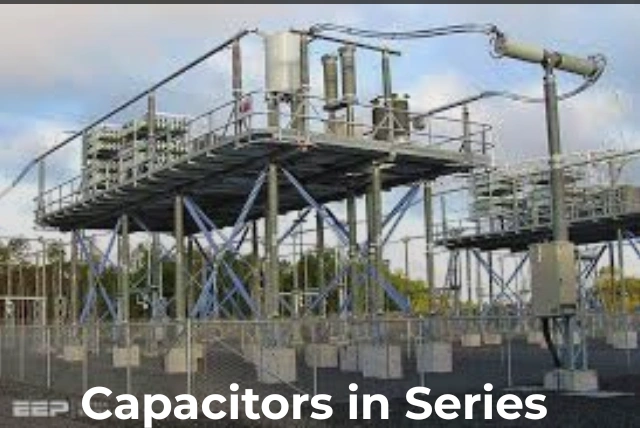
Capacitors are fundamental components in electronics. They store electrical energy and play key roles in filtering, timing, and power management circuits.
If you are a hobbyist, student, or professional engineer working on a project involving capacitors, it is important to understand how they behave when connected in series.
When capacitors are linked in series, they form a single path for charge flow. As a result, the same charge passes through each capacitor, but the total voltage is divided across them. In this configuration, the total capacitance decreases and becomes less than the smallest individual capacitor in the chain.
Why Connect Capacitors in Series?

Image source: pexels.com
When capacitors are connected in series—with the positive plate of one capacitor connected to the negative plate of the next—they behave differently from parallel arrangements.
From a voltage control perspective, the main advantage of a series connection is voltage sharing. The total applied voltage is divided among the individual capacitors. This makes it possible to handle voltages that exceed the rating of a single capacitor.
This approach is especially useful in high-voltage circuits, such as power supplies and audio amplifiers.
For readers in the UK, it is also important to consider electrical safety standards such as BS 7671 (IET Wiring Regulations). These regulations stress the importance of using components within their rated limits. Using capacitors in series can help ensure that no single capacitor exceeds its maximum voltage rating, reducing the risk of failure or safety hazards.
Safety Note
Image source: pexels.com
Working with high-voltage or mains-powered circuits can be dangerous. Always follow local electrical regulations, use properly rated components, and consult a qualified professional when working on high-voltage systems.
Key Formulas for Capacitors in Series

Image source: pexels.com
To use series capacitors effectively, the following formulas are essential:
Total capacitance (Cₜₒₜₐₗ):
1 / Cₜₒₜₐₗ = 1 / C₁ + 1 / C₂ + 1 / C₃ + …
This means the total capacitance is always less than the smallest capacitor in the series.
Voltage across each capacitor (Vᵢ):
Vᵢ = Vₜₒₜₐₗ × (Cₜₒₜₐₗ / Cᵢ)
If all capacitors have the same capacitance value, the voltage divides evenly among them.
Voltage Division: How It Works

Image source: pexels.com
Voltage control in series capacitors is based on the inverse relationship between capacitance and voltage drop. A capacitor with a smaller capacitance value experiences a larger voltage drop, while a larger capacitor drops less voltage.
This behavior is similar to a voltage divider, but it involves reactive components rather than resistors. Because of this, series capacitors are particularly useful in AC circuits, where voltage reduction is needed without significant power loss.
In real-world applications, small differences in leakage current can cause uneven voltage distribution. To address this, voltage-balancing resistors are often placed in parallel with each capacitor to ensure safe and even voltage sharing.
Practical Example

Image source: pexels.com
Consider a high-voltage filter connected to UK mains power (230V AC). The peak voltage can reach approximately 325V. A single capacitor may not be rated to handle this level safely.
By connecting two or more capacitors in series, the voltage stress is shared, allowing the circuit to operate safely within component limits.
Practical Applications of Series Capacitors

Image source: pexels.com
Capacitors connected in series are commonly used in many real-world applications, including:
-
Power supplies: In switched-mode power supplies, series capacitors help manage high input voltages from the mains.
-
Audio equipment: In amplifier coupling stages, series capacitors block DC while controlling signal voltage.
-
Renewable energy systems: Series capacitors are used to handle high and variable voltages in solar inverters or wind turbine controllers.
-
Timing circuits: Combined with resistors, series capacitors form RC networks used in oscillators and timing applications.
Using Online Tools for Series Capacitor Calculations

Image source: pexels.com
Using series capacitors for voltage control is a practical and effective technique for building safer and more reliable circuits. Whether you are experimenting at home or designing professional systems, understanding how these configurations work can significantly improve your results.
In addition to manual calculations, many engineers rely on online capacitor calculators provided by electrical component suppliers. These tools can help estimate total capacitance, voltage distribution, and component suitability, saving time and reducing design errors.
Sizing Balancing Resistors

Image source: pexels.com
Balancing resistors are only mentioned in passing in most guides, but they are what makes a series stack of electrolytic capacitors safe on DC. Each capacitor has its own leakage current, and on a DC supply leakage, not capacitance, sets how voltage divides at steady state. A capacitor that leaks less ends up with more voltage across it, possibly beyond its rating. Placing a resistor across each capacitor forces the division to follow the resistors instead. The rule of thumb is to choose resistors that pass several times the worst-case leakage difference, so the resistors dominate.
A Worked Example

Image source: pexels.com
Take two identical 470µF, 450V electrolytic capacitors in series on a 700V DC bus, so each should see about 350V. Choose a 100kΩ balancing resistor across each. The current through each resistor is 350V divided by 100kΩ, which is 3.5mA, comfortably more than the typical leakage mismatch of the capacitors. The power in each resistor is 350 squared divided by 100,000, about 1.2W, so a resistor rated at 2W or more is needed, and it will run warm. The series capacitance is 235µF.
Resistor Voltage Ratings Matter Too

Image source: pexels.com
A detail that catches people out: ordinary small resistors have a maximum working voltage as well as a power rating, and for many common quarter-watt parts it is only a few hundred volts. Putting 350V across one may exceed its voltage rating even if the power is fine. Use resistors specifically rated for the voltage, or split each balancing resistor into two or three in series to share the voltage. Check the datasheet rather than assuming that a resistor rated for the power is automatically rated for the voltage.
Discharging The Stack Safely

Image source: pexels.com
Series stacks on high-voltage DC can hold a dangerous charge long after power is removed. The balancing resistors also act as bleed resistors. In the example above, the total resistance is 200kΩ and the capacitance 235µF, giving a time constant of about 47 seconds. It takes around five time constants, roughly four minutes, for the voltage to fall below one per cent of its starting value. Always measure with a meter before touching, and use a proper discharge tool rather than shorting the terminals with a screwdriver.
Polarity And Non-Polar Stacks

Image source: pexels.com
Electrolytic capacitors are polarised and fail, sometimes violently, if reverse biased. In a series stack the positive terminal of one connects to the negative of the next. For AC use, two polarised capacitors can be connected back-to-back, negative to negative, to make an improvised non-polar capacitor, which is common in older audio crossovers, but a purpose-made non-polar or film capacitor is usually a better choice. Film capacitors have very low leakage and are often the better option for AC voltage division.
Supercapacitors Need Balancing Too

Image source: pexels.com
Supercapacitors have low individual voltage ratings, often under three volts per cell, so they are almost always used in series stacks, and they are particularly sensitive to overvoltage, which shortens their life dramatically. Passive balancing with resistors works but wastes energy continuously. Active balancing circuits monitor each cell and divert current only when needed, and most commercial supercapacitor modules include them. When building a stack, use matched cells and include balancing from the start.
ESR, Ripple And Heat

Image source: pexels.com
Capacitance and voltage are not the whole story. Each capacitor has an equivalent series resistance, and in a series stack the ESRs add, which increases heating under ripple current. Electrolytic capacitor life roughly halves for every ten degrees of temperature rise, so a stack that runs hot will fail early. Check the ripple current rating of each capacitor against the real circuit, keep stacks away from heat sources, and derate voltage to extend service life.
Measuring And Testing A Stack

Image source: pexels.com
Before relying on a series stack, measure each capacitor’s voltage under operating conditions with a suitably rated meter to confirm the balancing works. Measure capacitance and ESR of each capacitor individually with a component tester during assembly, and match similar values where possible. Recheck periodically in equipment that runs continuously, since electrolytic capacitors dry out and drift with age. For UK installation work, the IET’s wiring regulations referenced above set the safety framework.
Conclusion
Using capacitors in series is an effective way to control voltage and protect components in electronic circuits. By dividing voltage across multiple capacitors, this approach allows safe operation in high-voltage applications where a single capacitor would not be suitable.
A solid understanding of voltage division, real-world limitations, and safety practices helps ensure reliable and efficient circuit design, whether for learning, experimentation, or professional use.
Frequently Asked Questions (FAQs)
1. What happens when capacitors are connected in series?
When capacitors are connected in series, they all carry the same charge. The total voltage applied to the circuit is divided across each capacitor. The overall capacitance becomes smaller than the smallest individual capacitor.
2. How do you calculate the total capacitance of capacitors in series?
The total capacitance is calculated using this formula:
1 / Ctotal = 1 / C1 + 1 / C2 + 1 / C3 + …
This means the combined capacitance is always less than any single capacitor in the series.
3. Why is total capacitance smaller in a series connection?
In a series connection, the effective distance between capacitor plates increases. This reduces the ability of the circuit to store charge, resulting in lower total capacitance.
4. Do capacitors in series store the same charge?
Yes. In a series circuit, the same charge flows through each capacitor because there is only one path for current.
5. How does voltage divide across capacitors in series?
Voltage divides based on capacitance values. Smaller capacitors experience a higher voltage drop, while larger capacitors drop less voltage.
6. Can capacitors in series handle higher voltage?
Yes. Using capacitors in series allows the total voltage to be shared among them, making it possible to handle voltages higher than a single capacitor’s rating.
7. When should capacitors be connected in series?
Capacitors are connected in series when higher voltage handling is required, such as in power supplies, AC circuits, and high-voltage electronic applications.
8. What is the difference between capacitors in series and parallel?
In a series connection, total capacitance decreases and voltage is divided. In a parallel connection, total capacitance increases and the voltage across each capacitor remains the same.